Building the DIY Commodore C64 Diagnostic Harness
Do It Yourself C64/ DIY Diagnostic Harness - The Ultimate Diagnostic Solution
If you have the time and a some soldering skills, this kit can save you some money. It has all the components you need to assemble your own Diagnostic Harness!
This comprehensive Do it yourself C64Diagnostic Harness is designed to provide accurate testing and diagnostics for your Commodore 64. Whether you’re a collector, enthusiast, or technician, this kit ensures thorough checks of your system’s I/O connections. Here’s what’s included:
- Diagnostic 586220+ EPROM and 28-Dip Socket (Pre-programmed)
- Dead Test 781220 EPROM and 28-Dip Socket (Pre-programmed)
- User Port Module: Connects to the user port on your C64: 1 680 Ohm resistor,1 LED (color varies), and 1 Card Slot connector are included in the kit
- Cassette Port Module: Interfaces with the cassette port: 1 680 Ohm resistor, 330 Ohm Resistor, 150 Ohm Resistor, 1 LED (color varies), and 1 Card Slot connector are included in the kit
- 2 Controller Port Connectors: for testing the Game Controller ports: 2 680 Ohm resistors, 4 120K Ohm resistors, 2 LED (color varies), and 2 DB9 Female Connectors are included in the kit
- C64 Keyboard Dongle: For C64 keyboard connector testing: 1 680 Ohm resistor,1 LED (color varies), and 1 50-Pin Header connector are included in the kit
- Pre-assembled Serial Loopback: Essential for testing serial communication. This is already built and ready to go.
Features:
- Based on Sven Peterson’s design, this harness pairs seamlessly with the 586220+ diagnostic cartridges.
- Use it with the C64 Diagnostics cartridge to accurately test I/O connections.
- Refer to the original support manual for guidance on diagnosing any reported failures
These are instructions for building the DIY Commodore 64 Diagnostic Harness. The assumption is you have some basic electronics and soldering skills, here are the steps:
I: 2-in-1 Diagnostic/Dead Test Cartridge
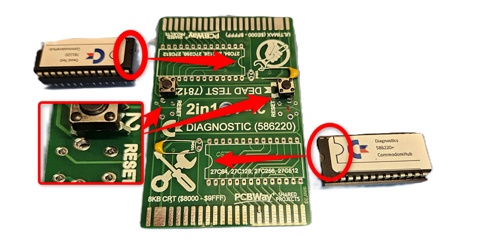
- Diagnostic and Dead Test EPROMs:
- Solder these with the notches going in the proper direction as illustrated in the picture.
- Solder these with the notches going in the proper direction as illustrated in the picture.
- 100ηF (0.1 μF) Capacitors:
- These capacitors are polarity insensitive, so they can be soldered in either direction.
- These capacitors are polarity insensitive, so they can be soldered in either direction.
- Reset Buttons:
- Pay attention to the direction you put the reset buttons in. If you’re having trouble, turn them 90° and try again.
- Pay attention to the direction you put the reset buttons in. If you’re having trouble, turn them 90° and try again.
- Dip Sockets:
- When soldering the dip sockets, be careful not to create solder bridges across contacts.
- When soldering the dip sockets, be careful not to create solder bridges across contacts.
II: User Port Dongle
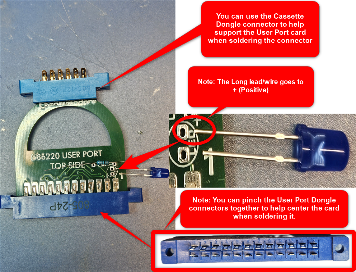
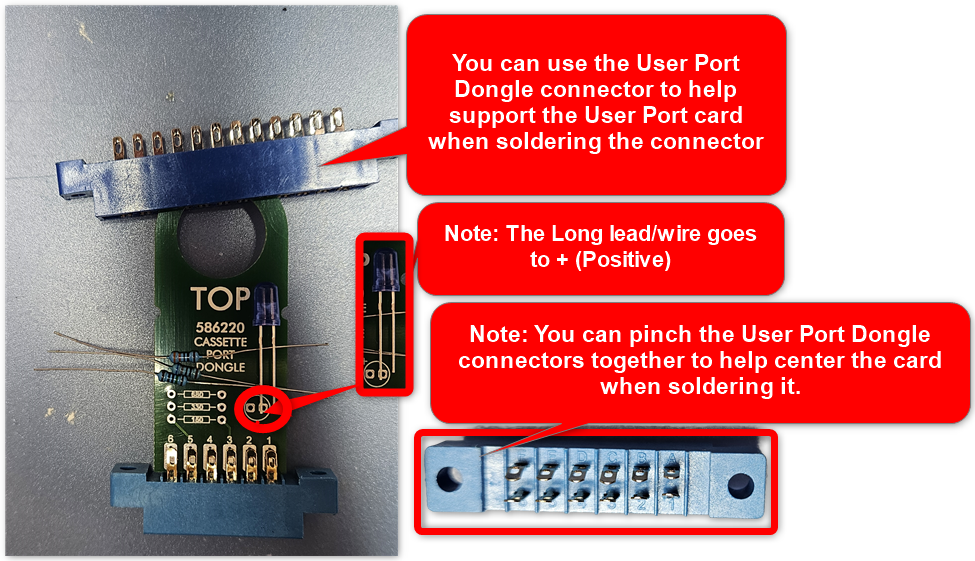
- Use the Cassette Port dongle connector to support and keep the User Port connector straight while soldering.
- Components:
- 1 × 680 Ω (ohm) resistor
- 1 × LED (Ensure the long lead/wire goes to + [Positive].)
- 1 × 680 Ω (ohm) resistor
- When soldering the connector, ensure the contacts are centered on the pad on the board and avoid solder bridges.
- Pinch the User Port Connector leads together slightly, leaving room to put the board in, to help center the board on the pins when soldering.
III: Cassette Port Dongle
- Use the Cassette Port dongle connector to support and keep the Cassette Port connector straight during soldering.
- Components:
- 1 × 680 Ω (ohm) resistor
- 1 × 330 Ω (ohm) resistor
- 1 × 150 Ω (ohm) resistor
- 1 × LED (Ensure the long lead/wire goes to + [Positive].)
- 1 × 680 Ω (ohm) resistor
- Center the contacts on the pad and avoid solder bridges.
- Pinch the User Port Connector leads together slightly, leaving room to put the board in, to help center the board on the pins when soldering.
Keyboard Connector Dongle
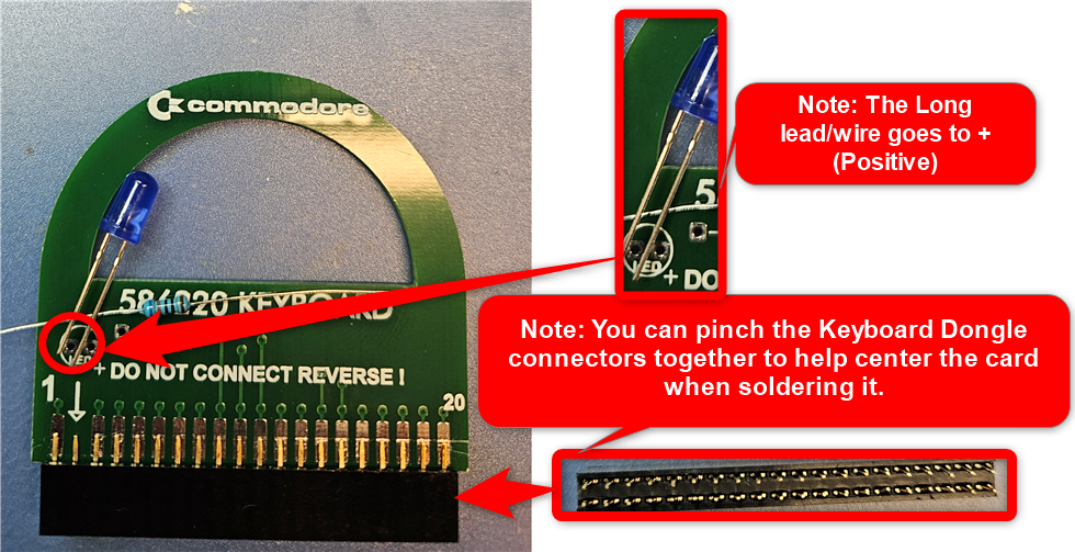
- Pinch the Keyboard Connector leads together slightly, leaving room to put the board in, to help center the board on the pins when soldering.
- Components:
- 1 × 680 Ω (ohm) resistor
- 1 × LED (Ensure the long lead/wire goes to + [Positive].)
- 1 × 680 Ω (ohm) resistor
- Center the contacts on the pad and avoid solder bridges.
- Note: The dongle connector has 2 rows, while the keyboard connector on the C64 has only 1 row. Either row can be plugged into the computer’s motherboard. Be mindful of Pin 1 on the motherboard and dongle.
- Note: The dongle connector has 2 rows, while the keyboard connector on the C64 has only 1 row. Either row can be plugged into the computer’s motherboard. Be mindful of Pin 1 on the motherboard and dongle.
- You can pinch the Keyboard Connector leads together a little bit, leaving room to put the board in, to help center the board on the pins when soldering.
NOTE: The dongle connector has 2 rows while the keyboard connector on the C64 has only 1 row. Having 2 rows helps with strength and stability on the board. Either row can be plugged in to the computer’s mother board. Don’t plug the dongle in backwards. Mind Pin 1 on the motherboard and dongle.
Control Port Dongles
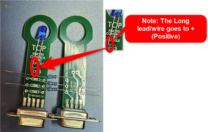
- Create 2 dongles, one for each Control (Joystick) port.
- Components for each dongle:
- 1 × 680 Ω (ohm) resistor
- 2 × 120K Ω (ohm) resistor
- 1 × LED (Ensure the long lead/wire goes to + [Positive].)
- 1 × 680 Ω (ohm) resistor
- Center the contacts on the pad and avoid solder bridges.
![]()
IV: Serial Dongle
When I ship this, It is already configured, you do not need to do anything to it.
Remember to follow these instructions carefully, and happy building! 🛠️🕹️
